


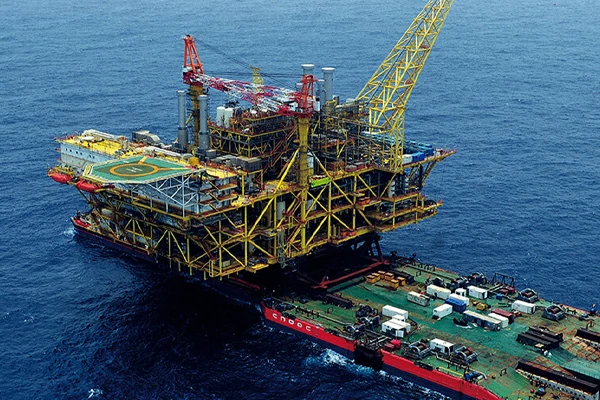
Higher kinetic energy
Larger design vessels and off-axis impacts increase the energy that must be dissipated without allowing mechanical bottoming-out.
Vessel anti-collision engineering
Tiered flexible protection for 100,000-DWT navigation channels, non-navigable approach spans and artificial-island transitions.
A full-watershed architecture combining floating composite structures, multi-stage energy absorption and intelligent submerged interception.
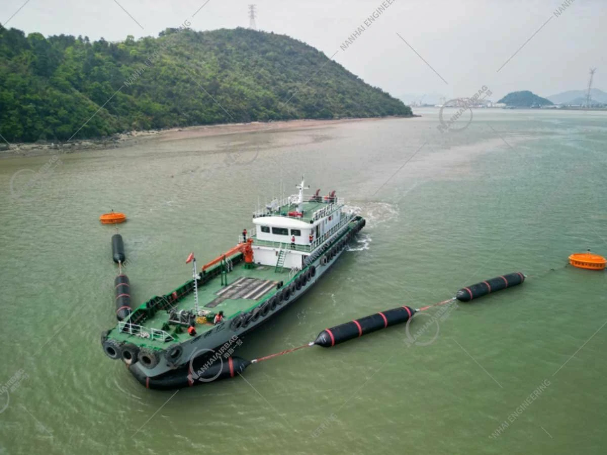
Why conventional protection falls short
A hard barrier can transfer an abrupt force spike into the pier while damaging the hull and crew. A compliant system must do three jobs at once: protect the structure, preserve the vessel and keep the waterway operating.
Larger design vessels and off-axis impacts increase the energy that must be dissipated without allowing mechanical bottoming-out.
Salt spray, UV exposure and wet–dry cycling can shorten the useful life of conventional steel protection and drive repeated overhauls.
Main-channel piers, slender approach columns and irregular island pile caps require different protection strategies and interfaces.
Installation and replacement must respect active navigation, tidal windows, marine access and environmental controls.
Full-watershed architecture
Rather than applying one standard fender to every pier, the protection strategy follows the vessel envelope, water depth, structural geometry and consequence of failure at each bridge section.
Heavy-duty composite floating units form a continuous 360° protection ring around high-consequence bridge piers.
A dual-layer strategy combines pier-mounted flexible units with an active barrier ahead of vulnerable low-clearance spans.
Custom-moulded units fit irregular, stepped or flared concrete contours that standard cylindrical fenders cannot follow.
How the energy is managed
Three mechanically distinct stages work in series to create a smoother, broader force plateau and reduce the peak reaction delivered to the bridge.
See the documented material data →Compliant surface deformation distributes contact pressure, cushions low-energy impacts and starts oblique-vessel redirection.
Internal cord-reinforced airbags provide a progressive, non-linear stiffness curve and high elastic rebound through long compression strokes.
At extreme impact, controlled cell-wall buckling and densification absorb megajoule-scale energy over a flat stress plateau.
Beyond the pier ring
Where a vessel can drift toward a low-clearance approach span, the intelligent submerged interception system creates a flexible barrier before bridge contact.
A 100m+ airbag chain rises across the vessel path.
Adaptive cylinders flip and deploy a bow-wrapping net.
Brake tethers release progressively to extend stopping distance.
 Field validation imagery · HZMB reference
Material & engineering data
Documented performance provides a starting point for tender review. Final material grades, energy capacity and compliance are confirmed for the project’s design basis.
| Property | Test reference | Documented performance |
|---|---|---|
| Outer rubber tensile strength | ISO 37 / ASTM D412 | ≥22.5 MPa, ≥85% post-age retention |
| Elongation at break | ISO 37 / ASTM D412 | ≥520% |
| Compression rebound | ISO 17357-1:2014 | ≥97.5% after cyclic 60% deflection |
| Closed-cell water absorption | ISO 2896 / ASTM D2842 | <0.8% by volume |
| Ozone / UV salt-spray resistance | ISO 1431-1 / ASTM B117 | No micro-cracking at 100 pphm / 168 h |
| Reported marine service life | Accelerated-age assessment | >20 years in subtropical splash zones* |
* Performance figures are drawn from NANHAI MARINE technical documentation and specific full-scale test or accelerated-age programmes. They are not a guarantee for every site. Final capacity, dimensions, material selection and compliance are established through project-specific engineering.
Flagship engineering reference
A 55-km cross-sea crossing through the Lingdingyang estuary, combining three navigation channels, more than 20 km of approach spans, two artificial islands and strict marine-operating constraints.
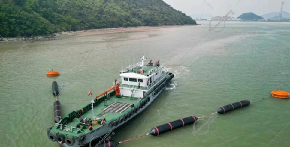
Main navigation channels · non-navigable approach spans · artificial-island transition pile caps.
Section-specific geometry, floating tidal compensation, staged energy absorption and modular marine replacement.
Evaluate vessel capture and controlled deceleration without relying on rigid impact against the bridge structure.
From design inputs to marine installation
Design vessel, speed, impact angle, pier geometry, bathymetry, tide and governing standard.
Concept sizing and coupled impact analysis to review force, stroke and energy balance.
Material selection, internal structure, mooring interface and custom mould design.
Factory assembly, balancing, quality records and preparation for marine transport.
Installation method, inspection points and individual module replacement planning.
Project questions
If your question depends on the bridge geometry or vessel envelope, include it in the project form and the team can respond against your case.
Ask an engineering question →Main-channel systems are sized around the project design vessel, transit speed and impact angle. The HZMB reference application documented a 100,000 DWT design-vessel capacity and a tiered architecture for navigable channels, approach spans and artificial-island transitions.
Useful inputs include design-vessel DWT and speed, pier geometry, water depth and bathymetry, tidal range, channel clearances, impact assumptions and the governing design standard.
No. The system combines a floating structural body, a multi-stage energy-absorbing core and project-specific mooring or interception components. It can be configured as a 360-degree pier ring, an approach-span barrier or a custom transition-zone unit.
Project discussions can reference AASHTO LRFD, EN 1991-1-7, PIANC guidance, JTG D60 and ISO 17357-1. The final design basis is confirmed against the tender and local authority requirements for each project.
The protection units use modular, factory-balanced construction intended for individual replacement. The final installation and replacement method is agreed with the bridge owner, port authority and marine contractor.
Submit the project consultation form on this page with your work email, company and application. The team will follow up with the technical white paper and, where relevant, a preliminary sizing discussion.
Request technical review
Share the project context below to request the white paper and a preliminary discussion on protection architecture, sizing inputs and next steps.
Your details are used to respond to this engineering request. For urgent tenders, email info@airbag.cc.
Related engineering resources